Assignment 3: Reflection
Reflection On Fuel Tank Project

The entire Assignment 2 crafting progress can be found under the link over here.
BEIL0014 Digital Making -- Assignment 2 Project: The 1:1 Scale Fuel Tank
Review On Stage 1: 3D Model & Assemble
At the step when we import our 3d fuel tank
model into Autodesk Slicer to prepare our fuel tank template for laser cutting,
we all discussed at that time that we need to make more rigid and harder
surface of tank template to hammer and shape the metal on the template.
 |
| Shape the metal piece on the tank tamplate |
The method we chose at that time is to
build the model using total 26 slices on both axis, which means 13 slices on
horizontal X and 13 slices on vertical Y. We thought total 26 slices for the
tank template is stable and solid enough, but we did not create the shell of
the tank. As a result, some template frames was snapped off when we hammer the
metal piece on it, which will be out of the shape and become inaccurate. After
all, we find out other groups all using masking tape to provide a smooth shell
to protect the template framework, which should be learned by our group.

Initial fuel tank template

Template after the project
Also, we used a total of 9 sheets of 3mm
plywood for making the tank template, the number of sheets can be seen as the
waste of materials and not environmental friendly.

Laser cutting the tank template

Material wastes
As we did not want the slices being too
difficult to slot together, we chose to ensure that the slot width is slightly
wider than 3mm. Also, we need the extra space for inconsistent material
thickness for putting glue between. So, we all agreed the slot width is set to
3.5mm. I found out some other groups did not consider this, as the result, they
required a lightweight hammer to force the sheets joining together, so it is
good for us to modify the width of the slot on the earlier stage in order to
assemble the pieces easier.

Choosing 3.5mm slot width
When we were making the 3d template model
in slicer, we did not leave of the gap on the back of the fuel tank, our group decided
to cut this gap off the metal piece at the end of the making process. The method
we did was cutting a paper template first from the fuel tank model and tape the
paper on the right position of the aluminium, then using the pencil to draw the
marking line and using tin snips to cut the shape off. But as this is at the
later steps when the aluminium piece is already hammered and curve at a good
shape, and the method using paper template for marking is something inaccurate,
it is quite hard to using tin snips to cut the straight line as we thought. The
border line of the gap shown on the final product is not satisfied by us, maybe
we leave the gap on the back of the model template on the earlier stage can
make the final product more accurate.

The border line of the back gap
Review On Stage 2: Metal Shaping
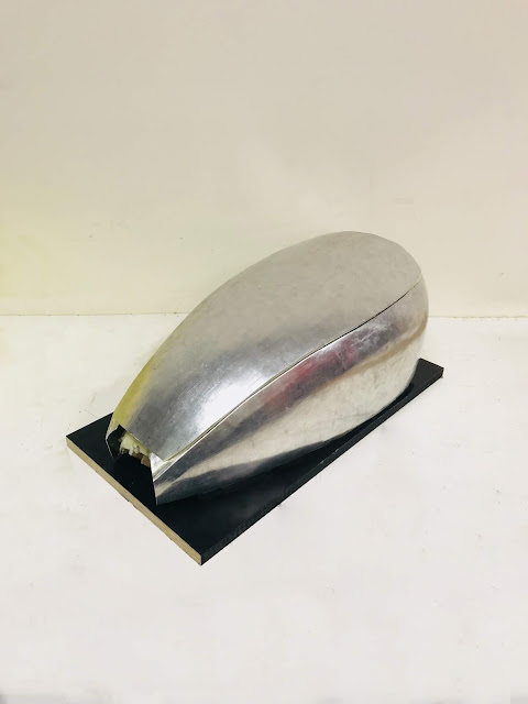
The piece I choose to make is the top piece
of the fuel tank, which is a large piece of the metal. The most significant
thing to consider is that it has a sharp curve on the two longitudinal sides
which can cover the left and right pieces under it, and a smooth curve along
the longitudinal axis. So, both curves on the perpendicular directions make the
top piece hard to shape, the tension and compression forces increased significantly
on the perpendicular directions when I hammered the metal piece.

Both curves on perpendicular axis
At the earlier stage, the most significant
problem I made is that I did not learn from the bowl making that drawing the
circular marking on the metal piece to guide me shape the curve. My method is only
using the paper template to draw the mark of boundary line on the aluminium. As
the result, I had to hammer the metal piece frequently between the fuel tank
template and the sphere stump or sand bag, it will waste lots of my time and
hard to shape the curve, especially comparing the bowl, the tank is much larger
and in a streamline shape.

Circular marking on the metal piece
The good technique I used at this step is when
cutting the aluminium, I left the extra space on the margin of pencil mark,
which will prevent the sheet shrink into smaller size after hammering it.
Also, I used 3 wood battens and 2 clamps to
make a simple bending tool on the table. Basically, my aluminium sheet
underneath the middle batten and bend the aluminium on the edge of the table to
make a good curve as my fuel tank template. The advantage of this bending tool
is that it won’t get the clear bending mark on the aluminium and will give me a
good curve of the aluminium on the longitudinal axis, also I don’t need much
effort to bend.

Using simple bending tool
After reviewing the process of hammering
the metal piece, I have been frustrated shaping both curve on perpendicular
axis of my top piece through the earlier process. As I strike a perfect
horizontal curve, the aluminium will become flat vertically and vise versa. It is
hard to find the balance of both perpendicular curves on the top part. Also, I
found it is difficult to make a good symmetrical aluminium for my top part,
because the sheet is too big to control the curve of the sheet, when striking
it will slightly tilt to one side and hard to adjust the shape.
But after the whole hammering process I find
out that the aluminium also has its own memory, if we did not hammer it to
enough extent, the curve of the aluminium sheet is not stable and will recover
to its original shape. This can be explained the problems I reviewed above when
hammering the curve of the metal piece. I did not hammer the sheet to enough extent,
the metal still has its own memory, and with the tension and compression
forces, the curve will recover quickly when I hammer on other places on the
sheet. Hence, as I spend more time on shaping the piece by hammering, the shape
become accurate and consistent to the shape of the template.

Hard to find the balance of both perpendicular curves
The most effective method I used through
the shaping process is cooperating with the hammer and English wheel. As I used
a lightweight hammer to tap softly, with continuous comparing with the
template. At the same time, keeping using the English Wheel a lot to smooth the
surface, which makes the model much smoother and shinier, and reduce the ugly hammer
marks.


Cooperating with the hammer and English Wheel
Also, we used a new tool which called the
bead roller for the both side parts of the fuel tank, tipping the contour line
of the top part on the side parts to make the top part edge perfectly covered
on the tipping line.


The use of bead roller
Another problem is that we did not polish the
fuel tank pieces this time, which leads our finished fuel tank do not look
shine enough and still can see some hammer mark on the surface.
Review On Stage 3: Teamwork
One of the greatest thing in our group is
that our members not only make our own part, we all cooperate with other
members and help them to shape their pieces. Almost in every photo that we took through the project, it always has one member help holding the metal piece on the tamplate while another hammering it, which I believe it is called turely teamwork.


As we all believe that even though
the fuel tank is built with different parts, but the fuel tank itself should be
seen as a whole, and each pieces of the tank should fit to each other. That is
why our group took much more time on building the tank pieces together and
every piece fits to each other, the whole fuel tank looks very smooth.


Teamwork

Final fuel tank

Comments
Post a Comment